Camera Calibration Toolbox: Unterschied zwischen den Versionen
| Zeile 163: | Zeile 163: | ||
mit | mit | ||
<math> \Phi</math>: Drehung um die x_W-Achse, Rollwinkel | <math> \Phi</math>: Drehung um die x_W-Achse, Rollwinkel | ||
Version vom 18. Mai 2014, 18:52 Uhr
Autor:
Dieser Artikel beschreibt die Arbeit mit der Camera Calibration Toolbox for Matlab von Jean-Yves Bouguet.
Matlab 2014a beinhaltet eine ähnliche Toolbox, aber bei diese Variante hat man die Möglichkeit den Quelltext nachzuvollziehen.
Installation
- Download der Toolbox
- Einbindung der Toolbox mit
Set Path. - Start der Toolbox mit
calib_gui.
Kalibrierung der Kamera
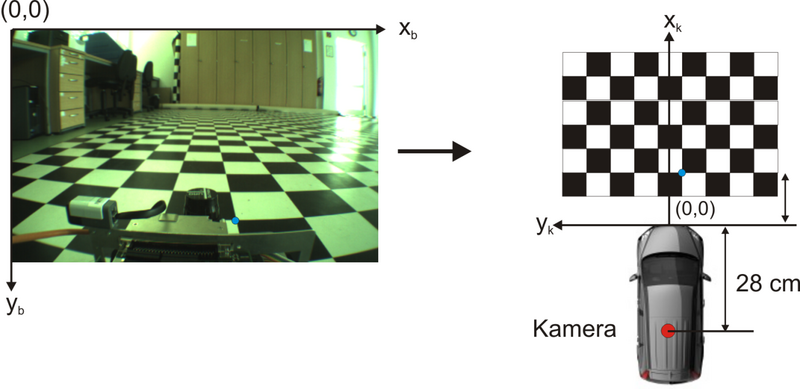
Kamera: VR Magic VRmDC Kamerahöhe: 0,27 m Nickwinkel: 11°
montiert auf den AMR2013 (dSpace)
- Bild laden laden mit
Read images
Basename camera calibration images (without number nor suffix): VRmDC_Boden
Image format: ([]='r'='ras', 'b'='bmp', 't'='tif', 'p'='pgm', 'j'='jpg', 'm'='ppm') t
Loading image 1...
done
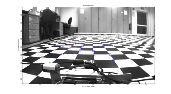
- Ecken extrahieren mit
Extract grid corners
Extraction of the grid corners on the images
Number(s) of image(s) to process ([] = all images) =
Do you want to use the automatic square counting mechanism (0=[]=default)
  or do you always want to enter the number of squares manually (1,other)? 1

Processing image 1...
Using (wintx,winty)=(5,5) - Window size = 11x11      (Note: To reset the window size, run script clearwin)
Click on the four extreme corners of the rectangular complete pattern (the first clicked corner is the origin)...
Number of squares along the X direction ([]=5) =
Number of squares along the Y direction ([]=5) =
Size of each square along the X direction: dX=16.6mm
Size of each square along the Y direction: dY=16.6mm   (Note: To reset the size of the squares, clear the variables dX and dY)
If the guessed grid corners (red crosses on the image) are not close to the actual corners,
it is necessary to enter an initial guess for the radial distortion factor kc (useful for subpixel detection)
Need of an initial guess for distortion? ([]=no, other=yes) y
Use number of iterations provided
Use focal provided
Estimated focal: 298.0959 pixels
Guess for distortion factor kc ([]=0): -0.1
Satisfied with distortion? ([]=no, other=yes) y
Corner extraction...
done
Hinweis: der Entstörungsfaktor kc liegt zwischen -1 .. 1.
- Führen Sie die kalibrierung mir
Calibrationdurch.
dies ergibt
Calibration results after optimization (with uncertainties):

Focal Length:          fc = [ 489.30363   512.03902 ] ± [ 18.88215   322.24042 ]
Principal point:       cc = [ 383.21579   233.25041 ] ± [ 0.00000   0.00000 ]
Skew:             alpha_c = [ 0.00000 ] ± [ 0.00000  ]   => angle of pixel axes = 90.00000 ± 0.00000 degrees
Distortion:            kc = [ -0.32665   0.10459   -0.00651   0.00219  0.00000 ] ± [ 0.04614   0.08993   0.00607   0.00190  0.00000 ]
Pixel error:          err = [ 0.32952   0.43539 ]

Note: The numerical errors are approximately three times the standard deviations (for reference).
Das Ergebnis basierend auf diesem einen Bild ergab intrinsische Kameramatrix K:
Anschließend wurde eine Kalibrierung mit einer vialzahl von Kalibrierbiildern durchgeführt diese ergab die nachfolgende Matrix.
Für die Koordinatentransformation wurden mit Hilfe der Camera Calibration Toolbox for Matlab die intrinsischen und extrinsischen Parameter der Kamera bestimmt.
Bei der Kalibrierung ergab sich für die intrinsische Kameramatrix A folgendes Ergebnis:
mit
- fokale Länge in x-Richtung in Pixel
- fokale Länge in y-Richtung in Pixel
- Position der optischen Achse in x-Richtung in Pixel
- Position der optischen Ache in y-Richtung in Pixel
Anzeige der Kameralage und Ausrichtung
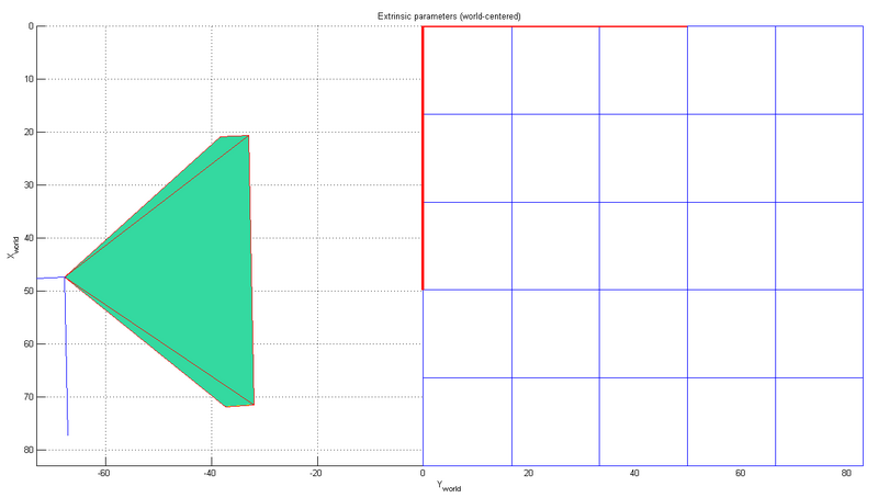
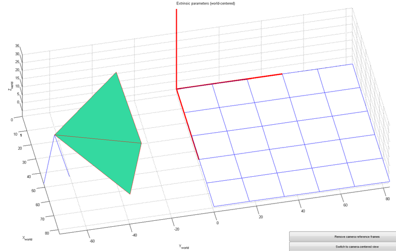
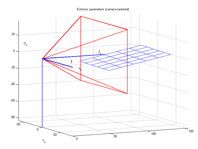
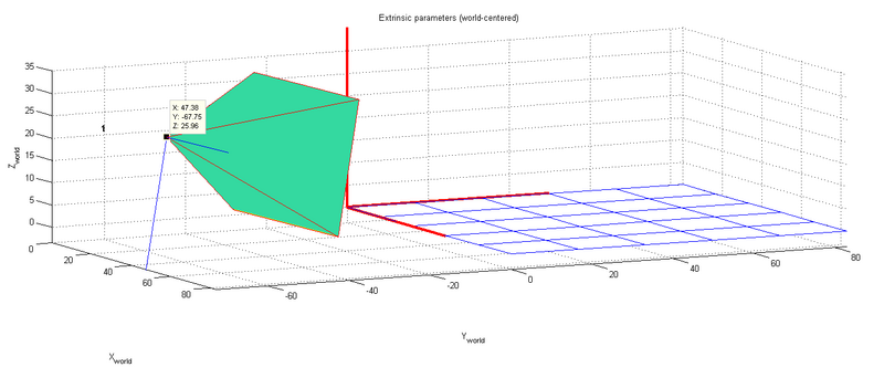
Show Extrinsic ermöglicht die Anzeige der extrinsischen Parameter.
Wichtig ist, dass das Koordinaten des Weltkoordinatensystems nicht dem üblichen Fahrzeugkoordinatensystem entspricht.
Die Position der Kamera im dargestellten Weltkoordinatensystem beträgt
Betrachten wir eine Szene im körperfesten Fahrzeugkoordinatensystem ist dieses am Mittelpunkt der Stoßstande definiert.
Der Verschiebungsvektor zwischen Kamerakoordinatensystem und Ort des Weltkoordinatensystems beträgt somit:
Verschiebt man das Weltkoordinatensystem mit dem in die Kamera, sind diese gegeneinander verdreht.
mit
: Drehung um die x_W-Achse, Rollwinkel
: Drehung um die y_W-Achse, Nickwinkel
: Drehung um die z_W-Achse, Gierwinkel
Berechnung extrinsischer Parameter
- Der Knopf
Comp. Extrinsicder GUI ruftextrinsic_computation.mauf. - Laden Sie die Kameraparameter Calib_Results.mat oder Kalibrieren Sie Ihre Kamera
- Sie werden aufgefordert die verzerrte Bilddatei zu laden.
Image name (full name without extension): VRmDC_Boden1
Image format: ([]='r'='ras', 'b'='bmp', 't'='tif', 'p'='pgm', 'j'='jpg', 'm'='ppm') t

Extraction of the grid corners on the image
Window size for corner finder (wintx and winty):
wintx ([] = 5) = 5
winty ([] = 5) = 5
Window size = 11x11
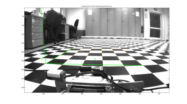
Click on the four extreme corners of the rectangular complete pattern (the first clicked corner is the origin)...
Could not count the number of squares in the grid. Enter manually.
Number of squares along the X direction ([]=10) = 5
Number of squares along the Y direction ([]=10) = 5
Size dX of each square along the X direction ([]=30mm) = 16.6
Size dY of each square along the Y direction ([]=30mm) = 16.6
Corner extraction...
Das errechnete Ergebnis lautet
Extrinsic parameters:

Translation vector: Tc_ext = [ -46.048515 	 13.733091 	 72.490486 ]
Rotation vector:   omc_ext = [ 1.753991 	 0.023825 	 -0.007702 ]
Rotation matrix:    Rc_ext = [ 0.999759 	 0.020374 	 0.008164
                               0.011740 	 -0.182129 	 -0.983205
                               -0.018545 	 0.983063 	 -0.182325 ]
Pixel error:           err = [ 0.42985 	 0.54546 ]
Der Rotationsvektor in deg beträgt
Der Translationsvektor
